ABS vs PVC Pipe – Pros and Cons

abs vs pvc pipe

ABS (acrylonitrile butadiene styrene) and PVC (polyvinyl chloride) are both plastics used as drain pipes, waste lines, and vent pipes. When comparing ABS vs PVC pipe, each has it’s advantages and disadvantages.

abs vs pvc pipe

Building Code Restrictions

Some building codes specify using one type of pipe over the other so make sure to check your local building code first.

Cellular/Foam Core vs Solid Core

You may see PVC or ABS pipe being sold as “cellular core” or “foam core.” This type of pipe is not solid. It is made with an inner PVC/ABS skin and an outer PVC/ABS skin with a foam/cellular core in between.

This type of PVC/ABS is cheaper and lighter than solid core pipes but is also less stiff and not as strong.

In this article, we will compare solid core ABS vs PVC pipe.

ABS Pipe

    • Black in color
    • Solvent cement only needed for joining
    • More shock/impact resistant, especially at colder temps
    • Easier to cut due to lower density
    • Home Depot 4″x10′ Schedule 40 solid core ABS specs*
      • OD 4.5″, ID 4″
      • 14 lbs
      • 176F max working temp
      • Not rated for pressurized uses
      • $18.87 at Home Depot (3/21)

PVC Pipe

    • White in color for most applications
    • Primer and solvent cement needed for joining
    • Slightly more chemically resistant
    • More flexible
    • Slightly more soundproof due to higher density
    • Home Depot 4″x10′ Schedule 40 solid core PVC specs*
      • OD 4.5″, ID 4″**
      • 20.55 lbs**
      • 140F max working temp
      • 220 psi rated pressure
      • $20.71 at Home Depot (3/21)

*Note that the example specs given above are only for one type of PVC and ABS pipe. It doesn’t mean that all ABS pipe isn’t pressure rated, for example.

**To calculate different weights and diameters for different schedule and different nominal size PVC pipe, check out the PVC pipe diameter calculator.

After all is said and done, there isn’t a huge difference between PVC and ABS pipe in drain, waste, and vent applications. PVC is definitely the more common of the two. But, as long as your building code allows it, either should work fine.

Thread Types – Bolts, Pipes, Hoses and More

thread anatomy

When purchasing a threaded pipe, hose or a bolt/screw of any sort, the many thread types can be overwhelming. Here’s a breakdown of the most common threads that are used today on different items around the house.

Just a heads up, this page contains affiliate links. If you buy through them I earn a small commission. If you chose to buy through these links I truly thank you for your support!   – Jake

In general, there are eight common thread types you may see around the house or garage:

    • Unified National/SAE (UNC/UNF/UNS)
    • Metric parallel
    • Metric tapered
    • National Pipe Thread Tapered (NPT/NPTF)
    • British Standard Pipe Parallel (BSPP)
    • British Standard Pipe Taper (BSPT)
    • Garden Hose Thread (GHT or NHR)
    • Type 1 (Used on propane tanks)

Aside from the obvious GHT and Type 1 threads, here are some things you may find these threads on:

    • Machine screws, bolts, and fittings
      • Unified National/SAE threads (UNC/UNF)
      • Metric parallel
    • Threaded pipe, hot water supply, faucet connector, flexible gas hose
      • National Pipe Thread Tapered (NPT/NPTF)
      • British Standard Pipe Parallel (BSPP)
      • British Standard Pipe Taper (BSPT)
    • Hydraulic Components
      • UNF, BSPP, BSPT, NPTF, Metric parallel, Metric tapered
    • Toilet Water Supply
      • Unified National (UNS)

Note – Wood screws, metal screws, masonry screws, and similar “pointed” screw thread types won’t be covered here.

Thread Anatomy

To understand different thread types it is best to first learn the anatomy of a thread:

thread anatomy

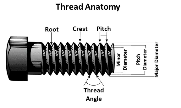
The root is the bottom of the “v” between each thread. The crest is the peak of a thread. The pitch, in metric threads, is usually measured as the millimeters between each crest. With standard threading, the pitch is measured in threads per inch (TPI). The major diameter is the diameter at the widest point of the threads.

It’s not shown in the above diagram, but tapered threads have a slightly narrower diameter near the tip and slightly wider diameter towards the head. The amount by which the threads taper is known as the taper angle.

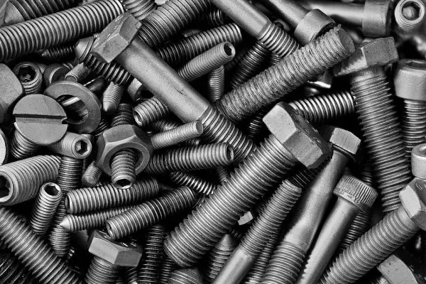
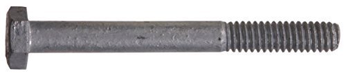
Machine Screws and Bolts Thread Types

These items will typically use Unified National (UN), or metric parallel threads.

The two most common types of Unified Threads are the UN Coarse (UNC) and UN Fine (UNF). ANSI B1.1 is the standard that defines how many threads per inch for any given diameter of UNC or UNF fastener.

The standard for metric parallel threads is given by International Organization for Standardization (ISO) 68-1, 261, 262, and 724. Metric fasteners also commonly come with coarse (1mm pitch) or fine (1.25mm pitch) threads.

Identifying Machine Screws and Bolts

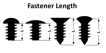
Machine screws and bolts are identified by the major diameter, pitch, and length.

In general, the length of any fastener is measured from the tip of the fastener to where the head of the fastener meets the mating surface (i.e. wood, metal, etc.). Here are a couple examples:

fastener length measuring

Standard and metric machine screws and bolts are notated slightly differently.

For example, a 3/8″ diameter hex bolt with 16 threads per inch and 1″ long is notated as 3/8 in.-16 x 1 in. A 12mm diameter metric bolt with 1.25mm pitch (fine threaded) and 35mm long is notated as an M12-1.25 x 35mm.

Take special note that metric threaded items may only list the pitch when it doesn’t have coarse threads (1mm pitch). For example, you may see a M14-1 x 35mm bolt listed as M14 x 35mm.

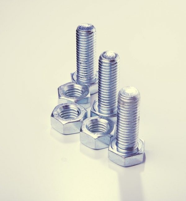
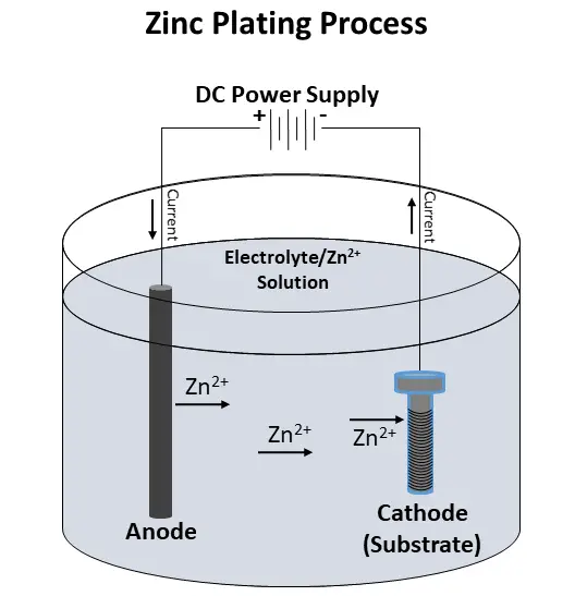
Machine screws and bolts are commonly zinc-plated or galvanized to resist corrosion. This is what gives them a shiny or dull gray appearance.

UN and Metric Thread Identification

You can identify UN and metric threads by using two simple tools, the pitch gauge and the calipers.

A pitch gauge like this one is cheap and extremely handy when trying to find a suitable replacement for a broken bolt or screw.

A digital calipers like the one shown below is a necessary tool for identifying the exact diameter and length of a screw or bolt.

Coarse vs Fine Threads

If you ever wonder when you should use fine threads and when you should use coarse threads, you aren’t alone. There are advantages of using each:

Coarse

    • Faster assembly
    • Minor thread damage is less likely to affect assembly
    • Less chance of stripping in weak materials (i.e. wood)

Fine

    • Higher tensile strength due to more surface area
    • Higher shear strength due to larger minor diameter
    • More precise adjustment
    • Easier to tap than coarse threads
    • Less tendency to loosen

Depending on the application and fastener requirements, coarse or fine threads may be a good choice based on the advantages given above.

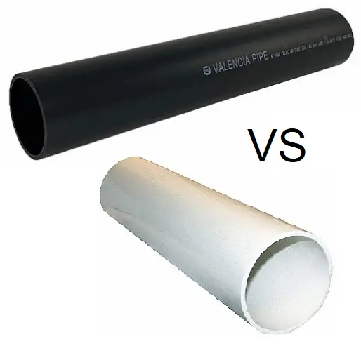
Threaded Pipe, Hot Water Supply, Faucet Connector, and Flexible Gas Hose Thread Types

Threaded Pipe Thread Types

If you live in the US or Canada, threaded pipes most likely have National Pipe Thread Tapered threads (NPT) or National Pipe Thread Tapered Fine threads (NPTF). These threads are described by the ANSI B1.20.1 and ANSI B1.20.3 standards.

NPT threads create their seal through a very tight seal between male and female threads, thanks to their taper. Always use a sealant tape or compound with these threads to ensure a good seal.

NPTF threads, on the other hand, don’t require the use of a sealant tape or compound. This type of thread has a root and crest shape that allows the threads to actually deform to create a mechanical seal. Another name for NPTF threads is Dryseal American National Standard Taper Pipe Thread.

If you don’t live in North America, chances are your threaded pipe uses British Standard Pipe Parallel (BSPP) threads or British Standard Pipe Taper (BSPT) threads. These thread types are based off the standards set in ISO 7 (taper) and ISO 228 (parallel).

Hot Water Supply, Faucet Connector, and Flexible Gas Hose Thread Types

Hot water supply lines, faucet connector hoses, and flexible gas hoses commonly use NPT threads. You may see threads on these items labeled as MIP/FIP (Male Iron Pipe or Female Iron Pipe). Just know that NPT and MIP/FIP are interchangeable.

Hydraulic Component Thread Types

Hydraulic component threads use many types of threads, depending on the fitting and application. UNF, NPTF, BSPP, BSPT, metric parallel, and metric tapered are all potential thread types used on hydraulic components.

Metric tapered threads are similar to metric parallel threads except the tapered threads are, obviously, tapered.

Identifying Hydraulic Component Threads

Parker Hannifin has a great guide on identifying hydraulic component threads.

Garden Hose Thread

Garden hoses and related fittings have their own type of thread called, unsurprisingly, Garden Hose Thread (GHT).

This thread type is officially known as National Hose (NH) thread and is based off the standards given in ANSI B1.20.7.

Male and female GHT threads may also be identified as MHT (Male Hose Thread) and FHT (Female Hose Thread), respectively.

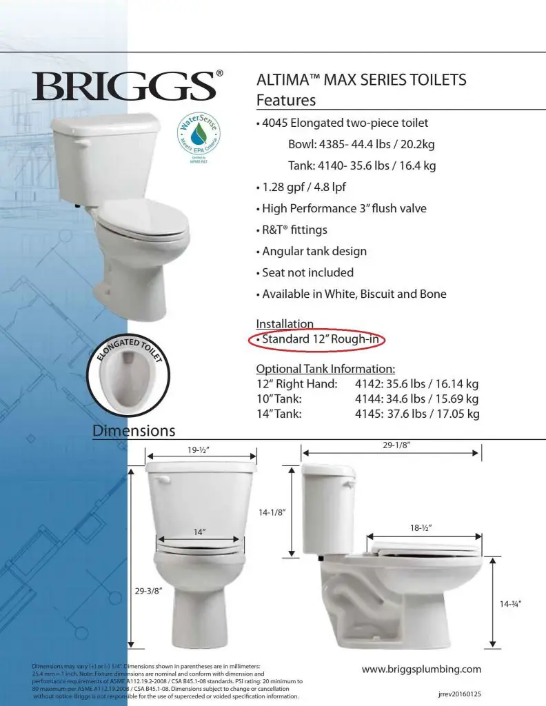
Toilet Water Supply Thread

Toilet water supply lines and related fittings have a type of thread known as 7/8″ Ballcock. This is a parallel thread type that is equivalent to 15/16″-14UNS thread.

Propane Tank Thread Types

A typical BBQ propane tank and hose commonly utilize a thread type called Type 1. However, there are other thread types propane components use as well. Etrailer has a great article on identifying thread and fitting types on propane tanks and accessories.

There’s no doubt that there are a ridiculous amount of thread types out there. This can lead to a lot of confusion on what is compatible with what. Just remember to always use the same thread type when replacing screws/bolts, fittings, hoses, etc. While it might seem like two different standards of pipe threads fit together, it’s just not worth the risk of a leak in the long run.


What is Zinc Plated and Galvanized Steel?

plain steel bolts

Zinc plated steel is plain steel that is coated with a very thin layer of zinc by using electricity. It’s main purpose is to prevent the steel from rust and corrosion.

Galvanized steel is also coated with zinc, but a different manufacturing process is used. Read on below to see the differences of galvanized and zinc plated steel.

It’s uses include many applications from bolts, screws, nails, washers, and nuts to brake rotors, chains, and pipe.

Zinc plated steel is easy to spot as it is usually shiny silver and slightly blue in color. Although, yellow zinc and black zinc plating also exist and can offer better corrosion resistance than “blue zinc”.

If you walk through the fastener isle at your local hardware store you will see a large amount will be zinc plated.

Typical zinc plating will take plain steel that looks like this:

plain steel bolts

And turn it into this:

zinc plated bolts and nuts

How is Steel Zinc Plated?

The zinc plating process varies slightly from manufacturer to manufacturer. However, the process described below is one used by Surface Treatment Experts and is typical of many manufacturers.

Cleaning

Materials to be zinc plated, aka substrate, are first thoroughly cleaned of any debris, corrosion, or oils.

Plating Solution

A plating solution, or bath, is then mixed up for the substrate to be immersed in. This bath is basically an electrolyte solution mixed with zinc ions (charged zinc atoms). Often there are other chemicals included as well. These chemicals adjust the speed and distribution of the zinc onto the substrate.

Electrodeposition

A DC current is then applied to the solution. The current flows from the anode to the substrate, which serves as the cathode. During this process, the zinc ions are deposited onto the substrate.  The current then flows back to the anode and the cycle repeats:

zinc plating process diagram

Post Treatment

Finally, the substrate is removed from the solution, rinsed, and dried. Passivation is a process often used to protect the zinc. This can also alter the final color. Sometimes, the substrate is sealed with a clear sealer as well to add extra corrosion protection.

Zinc Plating Thickness

The thickness of zinc plating ranges from 5 to 25 µm. One µm (micrometer) is 0.000001 meters.

The actual thickness depends on the standard to which is manufactured to. Listed below are four classes of zinc-plating, defined by ASTM B633:

    • Fe/Zn 5 (5 µm thickness)
    • Fe/Zn 8 (8 µm thickness)
    • Fe/Zn 12 (12 µm thickness)
    • Fe/Zn 25 (25 µm thickness)

Zinc Plated Steel vs Galvanized Steel

Galvanization is often used as a generic term for adding a zinc coating to a metal. In these cases, zinc plating would be a specific type of galvanization process.

Another common and more robust galvanization process is known as hot-dip galvanization. This process is used on fasteners, hardware, and building materials that will be exposed to the elements.

During the hot-dip galvanization process, metal parts are actually submerged in molten zinc. This provides a thicker and longer lasting coating than electrodeposition.

Hot-dip galvanized parts have a dull, flat grey appearance. Hot-dip galvanized steel looks like this:

hot dipped galvanized bolt

Zinc Nickel

Zinc nickel plating is a superior variation of zinc plating. Here, nickel gets combined with zinc in the electrodeposition process.

Although nickel increases the corrosion resistance, it is a more expensive process and therefore not as widely used.

Zinc Plated Steel Application Restrictions

High Temperatures

Zinc plated materials should not be used in applications where temperatures of 500°F and higher are achieved. This includes applications where parts will be welded. The zinc coating will create toxic fumes that can lead to serious health problems. Always make sure to remove any zinc coatings prior to welding.

Acidic and Basic Environments

Zinc coatings do not hold up well against acids or alkalis. Use different coatings, like powder or plastic coating, in these environments.

Marine Environments

The salty environment in many marine applications can inhibit zinc’s durability as well. Use other coatings in these environments.

Toilet Rough In Distance and Clearances

toilet rough in distance and clearances

In general, the toilet rough-in distance is 12″ from the center of the toilet flange to the back wall for a typical toilet. There should also be a minimum of 15″ from the centerline of the toilet to any wall or object on either side of the toilet. Finally, there should be a 21″ minimum clearance from the front of the toilet to any wall or object.

These restrictions come from the International Plumbing Code (IPC). Not all states follow the IPC, though.

Just a heads up, this page contains affiliate links. If you buy through them I earn a small commission. If you chose to buy through these links I truly thank you for your support!   – Jake

International Plumbing Code

According to the International Code Council, 35 states follow the International Plumbing Code. If you live in one of the following states that does not follow the IPC, please check with your local state code for the required minimum clearances:

Alaska—California—Hawaii—Idaho—Kentucky—Louisiana—Main—Massachussets—Minnesota—Montana—New Jersey—North Dakota—Oregon—South Dakota—Wisconsin

toilet rough in distance and clearances

Side to Side Toilet Clearance

Section 405.3.1 of the International Plumbing Code (IPC) states that the centerline of a toilet, urinal, or bidet should be at least 15″ away from any wall, partition, vanity, or other obstruction.

Front to Back Toilet Clearance

The distance from the back wall to the toilet flange is based off the size of toilet you have.

Most toilets will have a standard rough-in of 12″ like the one below. Make sure to check the spec sheet.

toilet spec sheet

This is measured from the finished wall to the center of the flange. So, make sure to add in the thickness of the finished wall (drywall, tile, etc) if you currently just have studs up.

If you do have a mismatch between your toilet and flange, you can either buy a toilet with a matching rough-in distance or purchase one of these nifty toilet flange offsets:


The IPC also states that there should be a minimum of 21″ in front of the toilet to any wall, partition, vanity, or other obstruction.

To figure this out when roughing in your flange, measure the distance from the center of the hole on the bottom of the toilet to the front edge of the toilet.

Then, add 21″ to this number. Let’s say you get 30″. Now, you need to make sure the center of your toilet flange is at least 30″ away from anything that will be in front of the toilet.

Note it is not required to have a 21″ minimum clearance when the door is open, only when it is shut. With that being said, make sure you have enough room to open the door without it hitting the toilet.

Toilet to Fixture Clearance

The IPC also states that there should be 30″ minimum from the center of the toilet to the center of another toilet, urinal, shower, or sink.

Toilet Compartment Minimum Size

The toilet compartment is the area the toilet is in. Think of it as a stall. The minimum sizes based in the IPC are:

    • 30″ wide by 60″ deep for floor mounted toilets
    • 30″ wide by 56″ deep for wall mounted toilets

Waste Line

When installing your waste line for your toilet, remember to give it enough slope to avoid clogs and backups. Use the drain pipe slope calculator for more details.

For more information on installing or replacing a toilet, view Lowe’s toilet installation guide.

What are the Max Watts on a 15/20 Amp Circuit?

15A circuit breaker spec sheet

What are the max watts on a 15 amp circuit or 20 amp circuit before the breaker will trip?

Let’s do the math.

Watts = Volts * Amps

Most homes in the United States have outlet voltages around 120V.

So on a 15 amp circuit, the maximum watts are 15A*120V =  1800 watts.

80% Rated Circuit Breakers

Many 15A breakers nowadays can handle 1800 watts (100% load) continuously like this one from Siemens:

15A circuit breaker spec sheet

However, some circuit breakers are rated at 80% of their current rating for continuous loads.

The NEC (National Electric Code) defines a continuous load as “a load where the maximum current is expected to continue for three hours or more.”

Section 384-16(c) of the NEC also states that a standard OCPD (overcurrent protection device) can be loaded to only 80% of its rating for continuous loads.

In this case, the max watts on a 15 amp circuit with a standard breaker are 0.8*1800 = 1440 watts.

20 Amp Circuit Breaker

The math is similar for a 20 amp circuit breaker.

Here the maximum watts are 20A*120V =  2400 watts for a 100% continuous current rated circuit breaker.

On a standard 20A circuit breaker rated for 80%, the maximum watts are 0.8*20A*120V = 1920 watts.

For more information on how the NEC describes circuit breaker loading, check out this article.

So, the answer is that for continuous loads of three hours or more it depends on the circuit breaker you have. For instantaneous loads though, a 15A circuit breaker can handle 1800 watts and a 20A circuit can handle 2400 watts.